Boost Converter Calculator Online
Home How Tos Theory Power Electronics DC-DC Voltage Converters 6212 Buck Converter - Component Calculator. It was last updated on Jun 13 2013.

Boost Converter Step Up Chopper Electrical4u
Here I will walk you step by step on designing your first boost converter and how the datasheet is your best friend when designing.
Boost converter calculator online. If we calculate load current 165 we get 32 amps therefore the inductors power-uplift is only 4 volts x 32 amps 128 watts. For this tutorial we will be using. An online calculator is here and a typical breadboard BELOW.
This guide was first published on Jun 13 2013. Three typical circuit the automatic calculation of the external components parameters to use. In this post we try to understand the method of dimensioning or calculating inductors in buck boost converter circuits in order to ensure an optimal performance from these devices.
Boost converter from a TI calculator generating 9 V from 24 V provided by two AA rechargeable cells. Another difference is that while calculating the capacitance value we consider Ts2 as the switching frequency doubles and hence. Just by looking at the equation for our MS current you can see that it will be quite low.
Saturation voltage of the output transistor. Rectangular pulses of voltage into an inductor result in a triangular current waveform. The minimum voltage of the input.
Designing a boost converter sounds complicated and intimidating well that was always my impression when it came to this topic in school. The design equations for which this calculator. For an example of complete power stage design see the schematic of 300W active CCM PFC pre-regulator.
Basic Calculation of a Boost Converters Power Stage Brigitte Hauke. Component Calculator for BUCK Converters. It is not intended to give details on the functionality of a boost converter see Reference 1 or how to.
Modeling and verification of dcdc Boost Converter 21 Operation of dcdc converter The dcdc converter we address here is a switching converter. This spreadsheet will calculate the values of the power stage components for a Buck switchmode power converter. Minimum desired output switching frequency.
Forward voltage drop of the diode. Buck converter topology. Ii CONTENTS ACKNOWLEDGEMENTS a ABSTRACT i TABLE OF CONTENTS ii LIST OF FIGURES iv CHAPTER 1 INTRODUCTION 1 11 RATIONALE 1 12.
6212 Buck Converter - Component Calculator. Low Power DCDC Application ABSTRACT This application note gives the equations to calculate the power stage of a boost converter built with an IC with integrated switch and operating in continuous conduction mode. Switching Converter Power Supply Calculator The following is a design tool which calculates the parameters for a buck converter boost converter or Buck-Boost Converter - Step-downStep-up or invertingThe calculator assumes that during the normal load the inductor is in continuous mode meaning that the inductor never fully discharges its current.
Well derive the various equations for the current and voltage for a boost converter and show the tradeoffs between. 6211 Boost Converter - Component Calculator. Specifically the dc-dc converter is a power electronics circuit which uses an inductor a transformer or a capacitor as an energy-storage element to convert electrical power from one voltage level into another voltage level by switching action.
Desired peak to peak output ripple voltage. Hence the inductor current ripple should be chosen as half which is 20 of each inductor current. We take the example of IC 555 boost converter and IC 555 buck converter typologies and try to understand the optimizing techniques through equations and manual adjustments for achieving the most optimal.
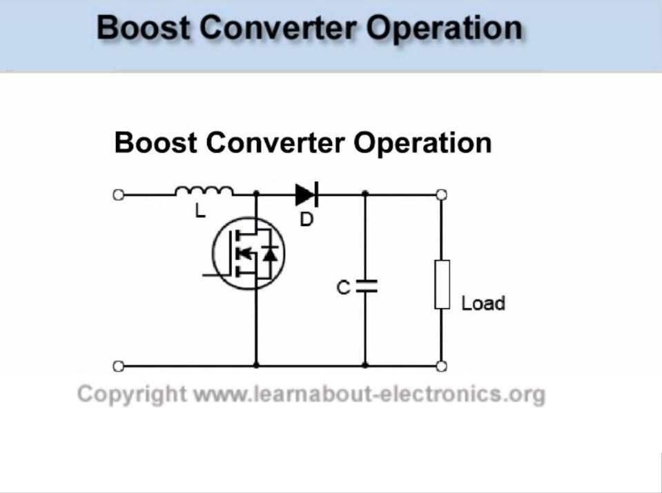
The converter uses a transistor switch typically a MOSFET to pulse width modulate the voltage into an inductor. Automatic calculation of peripheral component parameters for three typical circuits Instructions Just enter the parameters you want in the left middle box and click the Calculate and refresh the circuit diagram button. The square root of 12 is.
Enter the parameters you want in the left central box then click the Calculate and refresh schematic button to calculate automatically all relevant external components parameters and the corresponding. In the real world we would add-on a few watts for diode forward conduction losses. All aim calculations tests data and conclusions have been documented within this report.
A boost converter step-up converter is a DC-to-DC power converter that steps up voltage while stepping down current from its input supply to its output load. Simple boost converter. Compared to the single stage normal boost converter is in the calculation of the current ripple where the optimal value is chosen to be 40 of the load current 7.
This page The Calculator was last updated on Aug 20 2021. The user need only to fill in the input voltage output voltage load current switching frequency forward voltage drop of the rectifier and the on resistance of the switch. This online calculator will provide you with basic power relationship for the boost converter design.
It can automatically give all relevant peripheral component parameters and corresponding standard circuit drawings making the. The minimum voltage of the input. Results of simulation show that the switching converter will boost voltage from 5 volts to 15 volts with power conversion efficiency of 9416 percent.
Equations Topology. Saturation voltage of the output transistor. Calculating and calculating the split of RMS input current in boost SEPIC or choke converters is mostly an exercise in being thorough.
It is a class of switched-mode power supply SMPS containing at least two semiconductors a diode and a transistor and at least one. Forward voltage drop of the diode. In reality the design and testing of a boost converter is a lot easier than meets the eye.
The boost converter is a high efficiency step-up DCDC switching converter. Im going to ignore this because any decent boost-converter will raise its duty cycle D to accommodate diode losses. Thats because all these topologies have an inductor at their input that prevents higher MS current from cooking their input capacitors.
Boost Converter Design
Boost Converter With 2a Load Electrical Engineering Stack Exchange
Boost Converters
Boost Converters

Boost Converter Design Circuit Download Scientific Diagram

Buck Boost Converter What Is It Formula And Circuit Diagram Electrical4u
Boost Converter With 2a Load Electrical Engineering Stack Exchange

Estimating Transfer Function Models For A Boost Converter Matlab Simulink Example

The Calculator Diy Dc Dc Boost Calculator Adafruit Learning System
Boost Converter Design
Boost Converters

The Dc Dc Boost Converter Power Supply Design Tutorial Section 5 1 Power Electronics News

Boost Converter Matlab Simulink
Dc Dc Boost Converter Circuitlab
Boost Converters

An Introduction To Buck Boost And Buck Boost Converters Recom

The Dc Dc Boost Converter Power Supply Design Tutorial Section 5 1 Power Electronics News
Boost Converters

Dc To Dc Buck Boost Converter Circuit Homemade Electronics Circuit Circuit Converter
Post a Comment for "Boost Converter Calculator Online"